In the design and deployment of safety-critical assets within the automotive, aerospace, industrial automation, medical device, and energy sectors, ensuring safe and predictable operation is a primary engineering directive. While the terms "functional safety" and "reliability" are frequently used interchangeably in informal technical discussions, they represent distinct engineering disciplines with fundamentally different technical objectives, operational scopes, and mathematical frameworks.
Confusing these two concepts introduces significant architectural risk into a project. A system can be exceptionally reliable yet completely unsafe; conversely, a system can be structurally unsafe while maintaining high operational uptime. Developing robust safety-critical architectures requires a precise understanding of where these two domains diverge and how they synergize.
Technical Definitions and Engineering Frameworks
Functional Safety (FuSa)
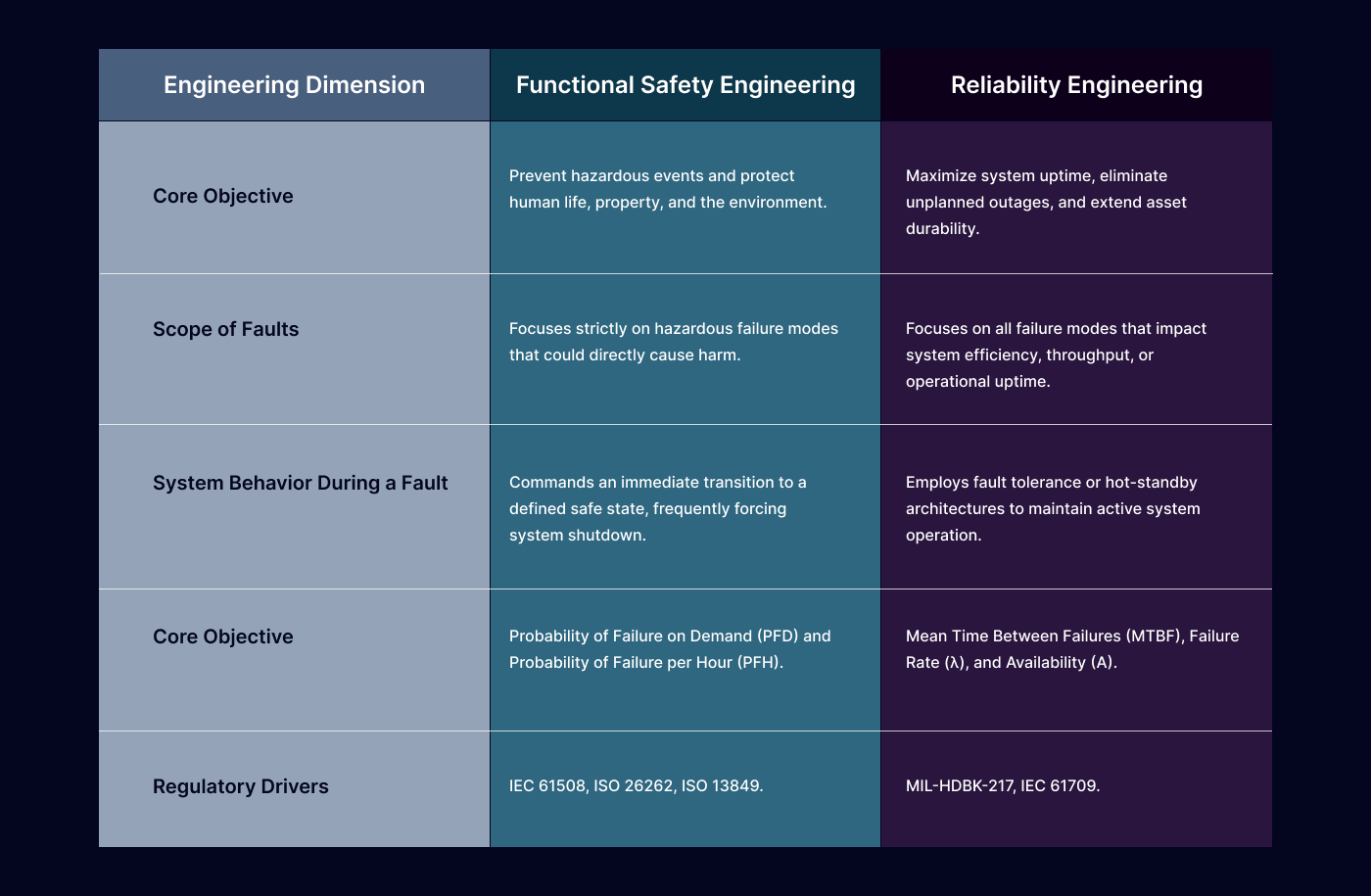
Functional safety focuses on ensuring that an electrical, electronic, or programmable electronic (E/E/PE) system executes its defined safety functions correctly under specified conditions, even when encountering internal random or systematic faults. The primary goal is to actively detect anomalies and command the system to transition into a predictable, controlled safe state, thereby preventing hazardous events or mitigating their consequences.
Functional safety is strictly regulated by sector-specific international standards, including:
IEC 61508:
The foundational standard governing industrial automation and general electronic systems, defining Safety Integrity Levels (SIL 1 to SIL 4).
ISO 26262:
The automotive derivative defining processes for road vehicles, establishing Automotive Safety Integrity Levels (ASIL A to ASIL D).
ISO 13849:
The machinery-specific standard evaluating safety-related parts of control systems using Performance Levels (PL a to PL e).
These standards enforce a rigorous, safe development lifecycle that mandates comprehensive hazard identification, risk assessments, the implementation of dedicated safety mechanisms, and independent verification and validation.
Reliability Engineering
Reliability engineering is a quantitative discipline defined as the probability that a system, subsystem, or component will perform its required mission function without failure over a specified operational duration under explicitly defined environmental conditions. While functional safety targets the mitigation of hazards, reliability engineering targets the optimization of operational performance by minimizing unplanned downtime and maximizing the durability and continuous operational lifecycle of the asset.
Core practices in reliability engineering include:
Failure Mode and Effects Analysis (FMEA):
Identifying potential failure typologies to improve system durability.
Reliability Block Diagram (RBD) Modeling:
Mapping parallel and series component dependencies to calculate overall system survival probability.
Root Cause Analysis (RCA):
Investigating mechanical or electrical structural failures post-mortem to execute design fixes.
Predictive Maintenance:
Utilizing real-time wear-and-tear monitoring to swap out components before an active fault interrupts operation.
Reliability is mathematically modeled using metrics such as Mean Time Between Failures (MTBF) or failure rates (λ), which quantify the temporal frequency of component degradation. Reliability predictions are governed by standards like MIL-HDBK-217 and IEC 61709, which focus on performance metrics, component stress modeling, and empirical calculation methodologies.
The Intersection of Safety and Reliability Data
Functional safety cannot exist without reliability metrics. Evaluating a system's Safety Integrity Level (SIL) under IEC 61508 or its Probabilistic Metric for random Hardware Failures (PMHF) under ISO 26262 requires raw component failure rate data (λ) supplied directly by reliability engineers. For example, the calculation of the Safe Failure Fraction (SFF) requires separating random hardware failures into safe failures (λs) and dangerous failures (λd).
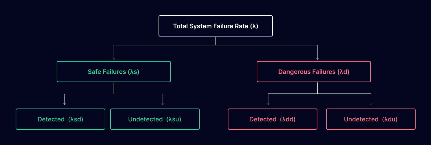
If a safety-critical component has a high failure rate (λ), it is highly unreliable. To maintain the required functional safety target, engineers must implement aggressive diagnostics or architectural hardware redundancy (e.g., a 1oo2 or 2oo3 voting logic scheme). This design integration ensures that if one component fails, the redundant backup or the diagnostic loop handles the failure safely.
Divergent System Failure Scenarios
To illustrate the architectural conflict between these two disciplines, consider a high-pressure chemical reactor vessel safety valve system.
Scenario A: High Functional Safety, Low Reliability
The system is designed using an aggressive fail-safe protocol. The control loop incorporates sensitive micro-electromechanical sensors that interpret minor signal fluctuations as an impending overpressure hazard. The system immediately trips the main isolation valve, venting the system and forcing a plant shutdown.
Outcome:
The system is perfectly safe because it consistently prevents explosions. However, it is highly unreliable, suffering from frequent nuisance trips and severe operational downtime.
Scenario B: High Reliability, Low Functional Safety
The system is designed using rugged, low-sensitivity components designed to prevent shutdown and maximize continuous fluid throughput. The architecture bypasses intermediate diagnostic alerts to maintain operational continuity.
Outcome:
The system demonstrates exceptional reliability and high operational availability over thousands of hours. However, if a genuine catastrophic pressure anomaly occurs, the safety functions may fail to actuate, resulting in a dangerous undetected failure and an explosion.
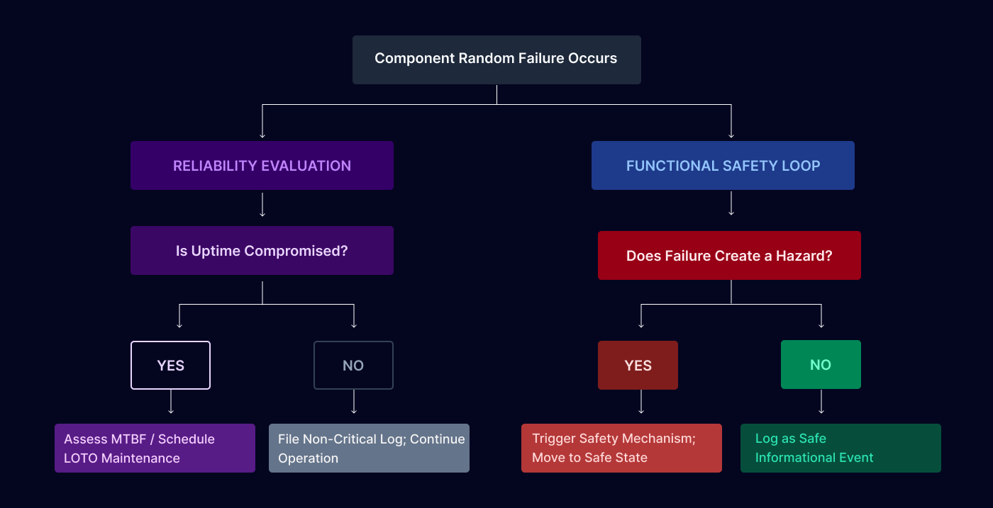
Functional Safety and Reliability Lifecycle Flow
The flowchart below documents how a system failure branches into distinct evaluation pipelines depending on whether it falls under the purview of reliability management or functional safety management.
Best Practices for Enterprise System Integration
Execute Collaborative Risk Assessments:
Reliability engineering teams must work alongside functional safety managers during the initial concept phase. Merging quantitative field data (MTBF) with qualitative hazard logs (HARA) ensures that the target SIL or PL requirements are physically achievable based on historical component performance metrics.
Co-Design for Reliability and Safety:
System architects must implement hardware redundancy and active diagnostics strategically. Utilizing diverse redundancy (e.g., pairing an optical sensor with an acoustic sensor) instead of identical redundancy protects the system against Common Cause Failures (CCF) while simultaneously improving reliability margins and safety validation metrics.
Deploy Unified Failure Analysis:
FMEA procedures should be expanded into Failure Modes, Effects, and Diagnostics Analysis (FMEDA). This unified methodology allows engineers to map out systemic wear-and-tear characteristics while identifying the exact diagnostic coverage (DC) required to satisfy functional safety compliance targets.
Maintain Bidirectional Documentation Traceability:
Every safety-critical component change must register across both documentation infrastructures. A hardware swap intended to improve uptime (reliability metric) must undergo an impact analysis to confirm it does not inadvertently degrade the loop response time or safety integrity required by standard audits.